The performance of the VK1RGI packet digi on 145.175 MHz was clearly degraded on its best, or capability, and so it has been replaced.. The original install was a 1990s TNC2 and a FM-828 PMR radio. FM828s make good split TX/RX radios and the individual TX and RX ports were diplexed into the existing 2+2 side mount dipole array used for the 146.950 voice repeater.
The new digi uses a Linux single board computer from Hardkernel called an ODROID XU-4. http://www.hardkernel.com/main/products/prdt_info.php?g_code=G143452239825
. The XU4 is a total and massive overkill for the job , but I had one already built up in a diecast shielded aluminium box and power supply so why not use it… I am using the eMMC storage option, while a bit more $$, it is much more reliable as a long term storage device on a remote site, and less/unlikely to suffer severe file system damage when the power is switched off while it is busy. Compare to SD card systems.
An Odroid C1 or C2 would be just fine, also.
The software on the XU4 is Debian flavor and the packet radio software is a package called DireWolf. The Debian Linux OS has the usual tweaks for reducing file system update access writes and also I have the clock turned down to 1 GHz to eliminate any peak load heat issues if I decided to run it at 100%.
Direwolf is a very well written open source package, and it also has first class documentation and a good user forum. It is the best there is, in my opinion. The source code is clear and well documented. The package provides for software FSK sound modems of all speeds 300-9.6k and beyond, digipeater, igate, locations beaconing, it does it all.
https://github.com/wb2osz/direwolf
The Odroid XU4 would run about 20 instances of direwolf ! Hence a C1 or c2 Odroid, or Pi 2 or 3 would be fine, also. On the XU4, direwolf application with the single 1200 baud VHF modem runs just a few % CPU .
For PTT I/O , I used the internal GPIO on the Odroid PCB, a single NPN transistor with a 4.7k resistor in series with the base, and also a 10k resistor from GPIO to ground – this ground resistor ensures that while the GPIO is not set as an IN or OUT during boot up phase, and thus floating, the PTT transistor is pulled to ground.
For sound, I used a $10 USB plug in sound card. A real cheap one with 3.5mm stereo connectors, and mic level input. I would recommend a slightly easier to connect one known as a UCA-222 on internet ebay circles that has RCA connectors and line level input.. With a mic level input be sure to turn the input mic boost off and capture mic level usually has to be all the way down..
Note that the Direwolf can run MULTIPLE modems and TNC nodes, and GPS recv etc . Just add more sound devices. Actually I think it can run separate modems on left and right channels. A startup script of many is installed and Direwolf runs at boot as a standard user with additional Audio and Real Time privilges. It’s a good idea to run alsamixer in the scripts to ensure the mixer I/O is set correctly. I use ALSA but Direwolf has support for OSS, also, though I have not used it.
I used a $2 ebay 6-20V in, 5V output 5A switchmode power supply to make 5V, and be sure to add 0.1uF (100nF) ceramic capacitors on the back of the two large electrolytic capacitors to reduce the conducted noise from the power supply. Note also the ferrite bead on the input power supply. This is required !
Radio: I used the most excellent Tait TM8000 series mobiles, available at low cost from some 2nd hand sellers on ebay, I buy mine from a company in the UK about about USD100. These radios have EXCELLENT receivers- the receivers are base-station grade, and have overload and strong signal handling performance 2nd to few . Highly recommended. The software is easy to program and the I/O is highly configurable all on a single DB15 on the rear of the radio . All combinations of audio tap points in the radio (pre/de emphasis, pre/post clipper, DC / non DC etc) are supported. Also they only draw about 2W on RX. But anything will work… I took time to carefully set up the modulation so that the 1200 and 2200 Hz tones were not clipped, that is the 2200 Hz tone was approx 5 dB MORE deviated than the 1200 Hz tone so they come out of a receiver flat when de emphasised.
Diplexing
Because the radio has a single T/R port and the original setup was a separate T/R port, the means of connecting it to the antenna system had to change. We have a spare VHF 4dB gain colinear on top of the mast, omni, just what we want, however being on the same mountain it requires careful filtering to not create or suffer interference from co located services.
A Bandpass-Notch 150mm diameter 1/4 wave filter (“cavity”) pass 145.175 (packet) and reject 146.350 (repeater RX) provided 52dB rejection of noise at the rpt recvfreq. Bandpass-Notch filters dont provide much ‘bandpass’ so an extra standalone bandpass filter is required to protect other uses on the comm site, and also protect itself from strong signals from other users that might contribute to overload / spurious products and interference….so, a bandpass only cavity at 145.175 was added in series with the pass/notch filter to provide substantial rejection out of band. It has 30dB of rejection 3MHz away and keeps on increasing… Approx 42 around 156 MHz where there are quite a few co sited hi-band services and ~ 60dB rejection at the airband frequencies.
The repeater receiver of course needs to reject the 145.175 packet TX, this pass-notch filter was already in the duplexor chain.
Additionally there is the physical isolation of the two antennas that further increases the isolation by another ~ 48dB.
What is required? At 146.350 – 145.175 = 1.175 MHz away, ideally 90dB of TX noise rejection is required, and we have 52 (pass/notch)+48 (ant-ant)+ 17 (bandpass) = 117dB. The repeater transmitter to packet transmitter isolation is 48dB (ant-ant) + 24dB (bandpass) = 72dB. plenty.
Control
This system being a linux box is remotely administered via an SSH connection via a ham-band 440 MHz IP link by RACOMM Rip-EX. This is a highly configurable , variable bandwidth IP link that can provide bit rates from 1 to 100 kbps, permitting operation down to -120dBm for those really hard links. http://www.racom.eu/eng/products/radio-modem-ripex.html
Being a remote site that takes 1.5 hours drive to get to and a bit of planning, and is nearly inaccessable in winter , there needs to be a alternative reset facility for the single board computer to initial a power disconnect and reconnect if I got it really messed up.
In the past I have used a touch tone sequence on the radio that would trigger a power interrupt for 3 seconds. In this case I have put a Barix Barionet 100 into service, an IP controlled analog in / out, relay I /O and BASIC code automated box in. Something just as suitable would be one of the 8 ch relay controllers from ebay. Note the 2ch ones of similar ilk do not have a web server.
The whole thing is battery power supplied, floating on a lead acid supply/charger. An old ADSL1 modem is used as a 4 port ethernet switch for connecting up the various IP ethernet devices and draws only about 3W.
How well does it work ? Sensational. Performance is at least 12-15dB better than before. A couple of reasons for this. 1) the radio it replaced was deaf and off frequency. 2) the Dire Wolf software modem is FAR FAR superior with weak signals.

Odroid XU4 in box with power supply, PTT PCB. Black USB cable goes off on the left to the sound device.

GPIO connections , ground , PTT1, PTT2. Don’t forget to add some 0.1uF capacitors in parallel with the electrolytic capacitors on that switch mode power supply PCB. With it they are noisy as hell.

TM8100 interface on DB15 . Ground, audio in, audio out, PTT in, carrier detect out

Barix 100 IO interface and DIN rail power distribution

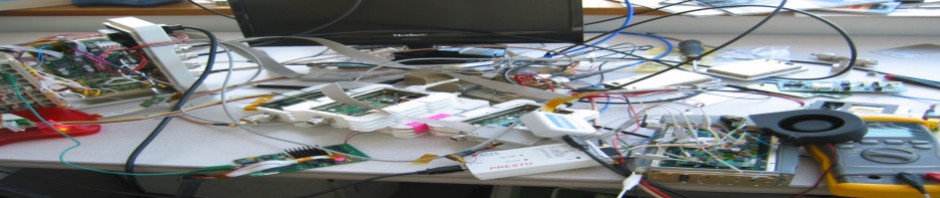
Installation. The Racom IP link is visible on the fore right hand side.
